Printreading for installing and troubleshooting electrical systems – Print reading for installing and troubleshooting electrical systems is a crucial skill for electricians and technicians. It allows them to interpret complex electrical diagrams and schematics, identify potential problems, and ensure the safe and efficient operation of electrical systems. This guide provides a comprehensive overview of print reading techniques, covering the fundamentals of electrical symbols and conventions, interpreting schematics and wiring diagrams, and using advanced techniques for troubleshooting electrical systems.
Print Reading Fundamentals for Electrical Systems

Print reading is a critical skill for electrical system installation and troubleshooting. It allows technicians to understand the design and layout of electrical systems, identify components, and trace circuits. Different types of electrical prints include schematics, wiring diagrams, and panel layouts.
These prints use symbols and conventions to represent electrical components and connections.
Interpreting Electrical Schematics
Electrical schematics provide a graphical representation of an electrical system, showing the components, connections, and flow of electricity. They use symbols to represent different electrical devices, such as resistors, capacitors, and transistors. Lines connect the symbols to show how the components are connected.
Labels identify the components and provide additional information, such as voltage and current ratings.
To interpret a schematic, technicians must be able to recognize the symbols and understand how they are connected. They must also be able to trace circuits to identify the path of electricity through the system.
Understanding Wiring Diagrams, Printreading for installing and troubleshooting electrical systems
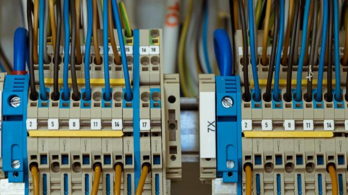
Wiring diagrams are similar to schematics but focus on the physical layout of electrical wires and connections. They show the location of electrical devices, junction boxes, and other components. Wiring diagrams use symbols to represent different types of wires and connections, and they may also include color coding to indicate the purpose of each wire.
To interpret a wiring diagram, technicians must be able to identify the symbols and understand how they are connected. They must also be able to trace wires to identify the path of electricity through the system.
Troubleshooting Electrical Systems Using Print Reading
Print reading plays a vital role in troubleshooting electrical system malfunctions. By studying the prints, technicians can identify potential problem areas and develop a plan for troubleshooting. They can use the prints to trace circuits, identify faulty components, and determine the cause of the malfunction.
To troubleshoot electrical systems using print reading, technicians must be able to interpret schematics and wiring diagrams. They must also be able to use a multimeter to test electrical circuits and components.
Advanced Print Reading Techniques
Advanced print reading techniques can help technicians to troubleshoot complex electrical systems more efficiently. These techniques include using tables and cross-referencing to find information quickly. Technicians can also create and use custom print reading tools to simplify the troubleshooting process.
Some software programs can also be used to assist with print reading and troubleshooting. These programs can provide features such as automatic circuit tracing and component identification.
Frequently Asked Questions: Printreading For Installing And Troubleshooting Electrical Systems
What are the different types of electrical prints?
There are several types of electrical prints, including schematics, wiring diagrams, panel layouts, and connection diagrams.
How do I identify components on a schematic?
Components on a schematic are identified by their symbols, which represent their function and electrical properties.
What is the purpose of a wiring diagram?
A wiring diagram shows the physical layout of electrical components and the connections between them.